
How to setup a simple Home Network using Ubiquiti Devices

Background
It can be tricky to design a home network that meets the needs of everyone while delivering consistent performance. This post documents my own home network and why I made the decisions that I did.
The scope and complexity of a home network setup will be driven by the size of your space and your requirements. We will summarize the requirements in the following categories:
How large a space needs to be covered?
How many levels needs to be covered?
Do any devices need to be hardwired?
Do any devices have any special performance requirements?
Are there any Internet of Things (IOT) devices that may need special consideration?
In this article I will be covering the first 4 and leaving the 5th for another article.
I will preface this by saying I probably did not have to upgrade my network components but did gain benefits by doing so. In previous years, I would use the router provided by my service provider with its built in Access Point. That was eventually upgraded to using an Asus router with custom firmware behind the ISP router. That allowed me to configure a VPN on the router and have all devices connected through the router to be automatically running through a VPN. If using VPN services such as Express VPN, it also allowed the flexibility of choosing which country the devices would appear in while on VPN.
I soon realized that this was quite effective for getting something like a Smart TV connected through VPN but that the overall internet performance was affected. I never did determine if configuration on my end was at fault, the router simply did not have the required horsepower or if the VPN service was the cause. It could have been a combination of the three, but I do know that VPN performance improved when running the software on a PC instead.
That was quite a few years ago and outside of trying to watch Netflix shows in another region, the real world need for something other than a PC to connect to VPN diminished. Eventually, I would only enable the VPN connection on the router when needed instead of at router boot. I then found that I tended to just watch shows available in my Netflix region and never use the VPN. This led to decommissioning the routing function of my Asus router (as well as the router based VPN) and using it only as an access point. This design was rock solid to the extent that it would run reliably for an entire year until the need to unplug it for some reason such as changing internet service providers occurred.
Initially, we lived in a 642 square feet condo and that meant there wasn’t really anywhere you could within the unit that didn’t have maximum Wi-Fi Performance. After moving to a 4 Level Townhome spanning 1800+ square feet, we had to rethink the placement of devices. The internet service is Fiber to the Home 1000MB down / 750MB up. This likely isn’t needed to achieve the requirements but the geek in me couldn’t resist. I will also be hardwiring as many devices as possible but given that the TVs have 100MB network interface cards (LG, I am looking at you) there won’t be much performance benefit and I am certain that everything could have been connected via WiFi and still achieve consistent performance. The building came prewired with Cat 5e from the basement to at least one point on each floor. I would have upgraded this to Category 6A or something else with higher performance limits but it appears to be glued in at some parts and it is unclear if there will be any real world benefits.
Objectives
The Objectives are as follows:
Achieve consistent connectivity from all devices.
No performance related issues for standard use cases, e.g. No buffering for TV Streaming, no delays in upscale to 4K HDR for TV streaming, no delays browsing from any device, no issues with conference calls etc.
No need to prioritize activities to maintain consistent performance. e.g. users watching 4k HDR streams on two TVs and another on a Skype call while browsing should not have their experience significantly affected by the hardwired PC uploading a 50GB file to YouTube. (How well these objectives are met will be covered in another article)
No downtime due to power outages
Architecture
The diagram below shows the general design of the network. All devices are connected to some form of power but I only highlighted power where a Uninterruptable Power Supply (UPS) was involved.

Network Architecture
Basement / Mechanical Room
The mechanical room will be the point where Fiber from the Service Provider enters the building. It is the white cable entering into the Bell device right below the Bell sign.

Network devices in the basement consisting of the ISP Router, Ubiquiti EdgeRouter X and Ubiquiti Cloudkey
A port on the ISP router is configured as a Demilitarized Zone (DMZ). That port connects to internet port of the Ubiquiti EdgeRouter X. Connecting two routers together in this manner will only work if they have different networks ranges configured on each. (e.g. 192.168.1.0/24 on one and 192.168.2.0/24 on the other, 192.168.1.0/24 on one and 10.0.0.0/8 on the other, etc.). This connection is shown by the red network cable from the EdgeRouter X to the Bell device.

The Ubiquiti Cloud Key is the white device shown above which facilitates configuration of the Access Point and Switch located on the 1st and 2nd levels respectively. The EdgeRouter X is configured independently.
Depending on your ISP, there may be ways to connect the EdgeRouter X or another router directly to your ISP bypassing their router all together.

There are 3 Ethernet ports in the mechanical room that run category 5e to each floor. Notice that the network cables run right next to the power cables from the breaker box. This is not recommended and should have some impact on performance, however negligible.

For some unknown reason, the developers thought it would have been a good idea to glue the cables into the ceiling on their run to the various levels as opposed to providing an easy way to service / replace them.

All devices connect to this 1000va UPS to ensure that internet connectivity stays up during power outages.
1st Level
The equipment on the first level is located in the living room in the same area as the television. The ethernet port on the living room level connects directly to a power adapter for the Ubiquiti Access Point, then to the Access Point which has an Ethernet pass through which is used to connect to a TV.

The Ubiquiti UniFi AP AC Pro Access Point located behind the television

The blue network cable from the port on the wall goes into the Power Adapter to send the data signal and power through the other cable to the Access Point

The access point’s PoE power adapter plugs into a UPS

The access point accepts the cable with PoE from the power adapter and also has a passthrough port which then has a cable which connects to the television

The cable from the passthrough port on the access point going into the television
2nd Level
The ethernet port on 2nd level goes into a room that is used as an office. It runs into the switch that is managed by the Ubiquiti Cloud Key.

Network Port in Office with Cat6A cable running to the 5 Port UniFi switch
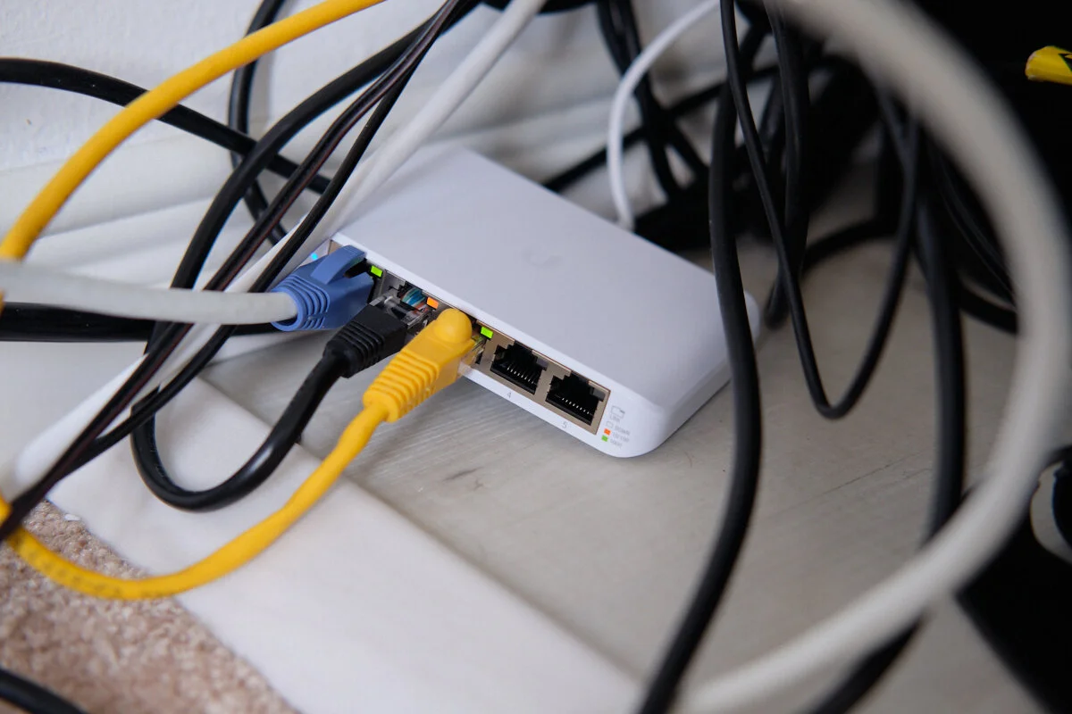
5 Port UniFi switch
There is no UPS here as the hardwired devices are a PC and a Television which are also not connected to a UPS. One will eventually be added.

Network cable running into the back of the PC
3rd Level
The 3rd level has two more rooms, one has a TV which is also hardwired and the remaining devices connect via WiFi.

The space between the furniture and wall was extremely tight so an angled network cable was used.

And plugged into the back of the television. LG only provides 100MB/sec ports on these televisions but that is more than enough for Netflix 4k HDR Streams or anything else the television would likely be doing
In another post, we will cover what can be monitored with this setup and look at a few performance statistics.